𐄀 Focus on providing PCBA separator manufacturing process solution

Quick Answer
Choosing the right PCB router bit for depaneling requires balancing tool diameter, PCB material, board thickness, cutting-path geometry, spindle speed, feed rate, cutting depth, and expected tool life. A smaller router bit can follow tighter contours but is generally less rigid, while a larger bit can offer greater strength and tool life but requires more routing clearance.
Spindle RPM and feed rate should always be evaluated together. Running at maximum RPM does not automatically produce a better PCB edge. The correct setting is the one that produces stable cutting, acceptable edge quality, controlled tool wear, and repeatable dimensions on the actual PCB material.
In router-based PCB depaneling, the milling cutter is a small consumable component with a major influence on production quality. An unsuitable or worn router bit can contribute to burrs, rough PCB edges, dimensional variation, excessive cutting force, tool breakage, or unnecessary machine downtime.
However, router-bit selection should not be treated as an isolated decision. The cutter works as part of a complete system that includes the spindle, collet, PCB fixture, machine motion, cutting program, dust extraction, and tool-management strategy.
This guide explains how PCB manufacturers can evaluate router-bit diameter, spindle speed, feed rate, tool wear, cutting depth, and tool-life management when setting up a repeatable PCB routing process.
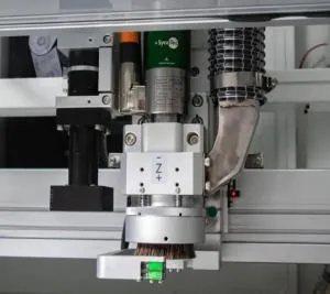
A PCB router bit, also called a PCB milling cutter or depaneling cutter, is a rotating cutting tool used to remove material along the programmed separation path of a PCB or PCBA panel. Router bits are commonly used to cut tabs, bridges, irregular outlines, curves, and other geometries that cannot be separated efficiently by straight-line V-scoring.
PCB routing tools are typically selected according to their diameter, cutting geometry, flute length, material, and compatibility with the spindle and collet. Because materials such as FR4 contain abrasive glass fibers, cutter condition changes gradually during production and should be monitored as part of process control.
If you are still deciding whether routing is the correct separation process, see our comparison of PCB depaneling methods.
Router-bit diameter is one of the first parameters to evaluate because it directly affects cutting-path clearance, minimum internal radius, tool stiffness, material-removal rate, and tool life.
| Router Bit Choice | Main Advantage | Main Consideration |
|---|---|---|
| Smaller Diameter | Fits narrower routing channels and smaller internal radii | Lower stiffness can make the tool more sensitive to deflection, runout, and excessive cutting load |
| Larger Diameter | Greater stiffness and potentially more robust tool life | Requires greater clearance and cannot follow very tight radii |
Practical Rule: Use the largest router-bit diameter that still fits the required cutting channel, internal radius, component clearance, machine collet, and PCB geometry. Then validate the tool on actual production samples.
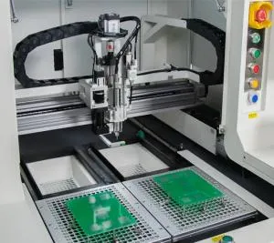
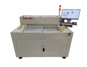
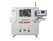
For example, the EXE 880 Offline PCB Depaneling Machine supports router-bit diameters from 0.8 mm to 3.0 mm. The correct diameter within that range still depends on the individual PCB and routing path.
The same router bit and cutting recipe should not automatically be used for every PCB material. Material hardness, reinforcement, copper distribution, board thickness, resin system, and thermal behavior can all influence cutter wear and cutting quality.
FR4 is one of the most common materials processed by PCB router machines. Its glass-fiber reinforcement is abrasive, so gradual cutting-edge wear is normal. Tool condition, feed rate, spindle speed, extraction, and cutting depth should be monitored throughout production rather than judged only from the first PCB.
Greater board thickness increases tool engagement and may increase cutting load. Cutter diameter, flute length, routing depth, PCB support, and feed rate should therefore be evaluated together.
Aluminum-core, high-frequency laminates, ceramic-filled materials, rigid-flex structures, and other specialty substrates should be qualified individually. Do not assume that a router bit and recipe validated for standard FR4 will deliver the same tool life or edge quality on a different substrate.
Spindle speed determines how quickly the cutting edges rotate through the PCB material, but maximum RPM should not be treated as a universal target. The spindle speed must be evaluated together with feed rate, router-bit geometry, cutting depth, PCB material, and tool condition.
Equipment manufacturer LPKF notes in its PCB cutting guidance that higher rotational speeds allow finer milling tools to be used, illustrating the relationship between tool size and spindle capability.
However, increasing spindle speed without adjusting feed rate can cause the cutting edge to remove too little material per revolution. Depending on the tool and material, this may increase rubbing and heat instead of improving cutting efficiency.
Feed rate is the speed at which the router bit moves through the PCB. If feed rate is too high for the selected cutter and material, tool load can increase and may contribute to deflection, rough edges, or cutter breakage. If feed rate is too low relative to spindle speed, the tool may spend more time rubbing against the material rather than cutting efficiently.
This is why a single statement such as “60,000 RPM is the best PCB routing speed” is misleading. Two factories may use the same spindle RPM but achieve very different results because their router-bit diameter, PCB thickness, cutting depth, feed rate, fixture, and material are different.
External Engineering Reference
Router-tool manufacturer PreciseBits publishes FR4 router-bit feed and speed reference data and specifically recommends performing a material-specific “sweet spot” test rather than applying one setup to different substrates or cutters.
| Parameter | What to Evaluate |
|---|---|
| Router Bit Diameter | Routing-channel width, internal radius, tool stiffness, component clearance |
| Spindle Speed | Edge quality, cutter behavior, spindle load, heat, and compatibility with feed rate |
| Feed Rate | Cutting load, cycle time, burr formation, tool deflection, and breakage risk |
| Cutting Depth | PCB thickness, flute engagement, usable cutting edge, fixture clearance |
| Tool Runout | Cutter stability, dimensional consistency, vibration, and uneven wear |
| PCB Support | Board movement, vibration, mechanical stress, and routing accuracy |
| Dust Extraction | Chip evacuation, recutting debris, machine cleanliness, and cutter environment |
Router-bit wear is not always obvious from visual inspection alone. In production, deterioration often appears gradually through changes in PCB edge quality, dimensional consistency, machine load, or cutting sound.
| Warning Sign | What It May Indicate |
|---|---|
| Increasing Burrs | Cutter edge wear, unsuitable cutting parameters, or poor support |
| Rough PCB Edge | Tool wear, vibration, spindle condition, or unsuitable feed/speed relationship |
| Dimensional Drift | Tool wear, runout, deflection, or machine/fixture positioning variation |
| Higher Cutting Load | A dull cutter may be removing material less efficiently |
| Frequent Tool Breakage | Excessive engagement, poor tool clamping, runout, unsuitable feed rate, or incorrect router-bit selection |
There is no universal number of PCBs or meters of routing that defines router-bit life. A cutter may wear differently depending on PCB material, copper distribution, board thickness, cutting length, tool diameter, spindle runout, feed rate, routing depth, dust evacuation, and fixture stability.
For this reason, tool replacement should be based on a validated production limit rather than simply waiting for the cutter to break. Manufacturers can track route length, number of panels, edge-quality inspection, dimensional results, alarms, spindle load, or other measurable indicators.
Important: Do not use a competitor's published tool-life number as your own replacement interval. Tool life should be validated on the actual PCB, cutter, machine, fixture, and production recipe.
If the PCB always contacts exactly the same vertical section of the milling cutter, that small section of the cutting edge will wear faster while other usable areas of the flute remain relatively unused.
Machines with segmented cutter-use or Z-axis depth compensation can distribute routing across different usable sections of the tool. This can improve utilization of the cutting edge, provided that flute length, fixture clearance, PCB thickness, and machine setup allow the depth change safely.
The EXE 880, for example, supports segmented milling-cutter usage and automatic down-cutting compensation as part of its tool-management functions.
Router-bit breakage is usually a process symptom rather than a problem that should be solved simply by installing another cutter. When breakage becomes frequent, the complete routing setup should be reviewed.
Feed rate is too aggressive for the tool and PCB material.
Router-bit diameter is too small for the required cutting load.
Cutting depth or flute engagement is unsuitable.
PCB support allows excessive movement or vibration.
Spindle or collet runout creates uneven tool loading.
Routing debris is not removed effectively and is being recut.
The cutter has already exceeded its validated wear limit.
Tool insertion, clamping, or handling has damaged the router bit.
1. Select the Appropriate Tool Diameter: Avoid choosing a smaller cutter than the PCB geometry actually requires.
2. Validate RPM and Feed Rate Together: Test cutting quality, cycle time, and tool condition instead of maximizing one parameter independently.
3. Control Spindle Runout: Maintain the spindle, collet, and tool-clamping system so the cutter rotates as concentrically as practical.
4. Use Stable PCB Fixturing: Board vibration and movement increase cutting variation and can increase mechanical load on the router bit.
5. Remove Routing Dust Effectively: Efficient extraction helps prevent debris from remaining around the cutter and cutting path.
6. Use Available Cutting-Edge Length: Where the machine and process allow it, segmented depth management can distribute wear across more of the cutter flute.
7. Replace Tools Before Quality Drifts: Establish a validated replacement limit based on production data rather than waiting for catastrophic tool failure.
| Problem | Possible Cause | What to Check |
|---|---|---|
| PCB Edge Burrs | Worn cutter, unsuitable feed/speed, poor support | Tool wear, RPM, feed rate, fixture, cutting direction |
| Router Bit Breakage | Excessive load, insufficient tool stiffness, runout, poor clamping | Diameter, engagement, collet, spindle, feed rate |
| Rapid Tool Wear | Abrasive material, rubbing, debris recutting, repeated use of one flute section | Material, feed/speed, extraction, Z-depth strategy |
| Cutting Deviation | Tool deflection, runout, fixture movement, worn cutter | Tool diameter, spindle condition, fixture, tool life |
| Excessive Heat | Tool rubbing, unsuitable feed/speed relationship, dull cutter | Cutter condition and validated process parameters |
Related Guide: Router-bit condition is only one factor affecting PCB edge quality. Learn how machine stability, spindle performance, CCD alignment, fixturing, and dust extraction work together in How Does a PCB Depaneling Machine Achieve Clean and Precise Cuts?
There is no universal best diameter. Use the largest cutter that fits the required routing channel, corner radius, component clearance, spindle collet, and PCB geometry. Smaller tools provide tighter routing capability but generally have lower stiffness.
The correct spindle speed depends on router-bit diameter, tool geometry, PCB material, feed rate, cutting depth, and machine configuration. For example, the EXE 880 has a maximum spindle speed of 60,000 rpm, but the actual production setting should be validated for the specific PCB.
Premature breakage can result from excessive cutting load, unsuitable tool diameter, spindle runout, poor collet condition, excessive engagement, incorrect feed rate, fixture movement, debris recutting, or using the tool beyond its validated wear limit.
Replacement intervals should be established through production validation. Manufacturers can use route length, number of panels, edge-quality inspection, dimensional results, spindle load, alarms, or other process data to establish a controlled tool-life limit.
Do not assume that one cutter and process recipe will perform equally on different materials. FR4 and metal-core boards create different cutting loads and wear conditions, so tool selection and process parameters should be separately qualified.
No. Spindle RPM must be matched with feed rate, cutter geometry, cutting depth, and PCB material. Excessively high RPM combined with an unsuitable feed rate may increase rubbing and heat rather than improving the cut.
PCB router-bit selection is a process-engineering decision rather than simply a choice of tool diameter. Cutter size, PCB material, spindle RPM, feed rate, cutting depth, runout, fixturing, dust extraction, and tool-life management all influence routing quality and production stability.
The most reliable approach is to begin with a tool that fits the PCB geometry, establish conservative process parameters, qualify the setup on actual boards, and then monitor edge quality and tool condition throughout production.
For manufacturers using automated PCB routing, tool monitoring and segmented cutting-depth management can further improve process control and help make better use of the available router-bit cutting edge.
Need Help Setting Up Your PCB Routing Process?
Send EXE your PCB material, thickness, panel drawing, routing channel, component clearance, production volume, and cutting requirements. Our team can help evaluate the appropriate PCB depaneling machine and routing configuration for your application.
Request a PCB Routing Evaluation