𐄀 Focus on providing PCBA separator manufacturing process solution

Quick Answer
A PCB depaneling fixture or PCB router jig holds and locates a PCB or PCBA panel while a router removes tabs or follows the programmed separation path. A well-designed fixture should keep the panel and separated boards stable without interfering with bottom-side components, the router bit, dust extraction, or automated material handling.
There is no single fixture design that is suitable for every PCB. The correct solution depends on panel geometry, component height, tooling holes, tab positions, board stiffness, router access, production volume, loading method, and the configuration of the depaneling machine.
The performance of a PCB router depends on more than spindle speed and cutting accuracy. During depaneling, the PCB panel must remain correctly positioned while the cutting tool removes material and progressively releases individual boards from the panel.
If the fixture does not provide suitable support, the panel may move, vibrate, tilt, or lose support as the final tabs are cut. At the same time, an overly restrictive fixture can create other problems, such as interference with tall components, insufficient router-bit clearance, difficult loading, or poor dust-extraction airflow.
PCB tooling specialists therefore design routing fixtures around the real PCBA geometry rather than only the outer PCB dimensions. For example, AGI's PCB router tooling guidance describes the use of locating pins, PCB support, bottom-side component masking and clearance for the router bit as important fixture considerations.
A PCB depaneling fixture is a custom or semi-custom workholding structure used to locate and support a PCB panel during router cutting. The terms fixture, jig, routing fixture, and depaneling tooling are sometimes used interchangeably in electronics manufacturing, although fixture is usually the more precise term for workholding.
The fixture is not responsible for cutting the PCB. Instead, it creates repeatable mechanical conditions so the machine's programmed tool path can be applied to the actual panel.
| Fixture Function | Why It Matters During PCB Routing |
|---|---|
| Positioning | Provides a repeatable relationship between the PCB panel and the programmed router path. |
| Board Support | Helps limit unwanted movement, vibration, or flexure while tabs and routing channels are cut. |
| Component Clearance | Prevents the fixture from contacting bottom-side components or other sensitive assembly features. |
| Router Access | Provides clearance around tabs and programmed cutting paths so the router bit and spindle assembly do not interfere with the tooling. |
| Separated PCB Retention | Helps prevent individual boards from shifting or lifting after their final tabs are removed. |
| Dust Management | Fixture openings and extraction paths can influence how routing debris is removed from the cutting area. |
Fixture design and PCB panelization are closely related, but they are not the same engineering task.
| Topic | Panelization | Depaneling Fixture |
|---|---|---|
| Primary Purpose | Defines how individual PCBs are arranged and connected within the manufacturing panel. | Holds and supports that panel during the actual separation process. |
| Typical Features | Rails, tabs, mouse bites, V-score lines, fiducials and tooling holes. | Locating pins, nests, support surfaces, relief pockets and router clearances. |
| Engineering Stage | PCB and panel DFM. | Manufacturing tooling and process setup. |
Related DFM Guide: If you are still defining the PCB panel itself, review our PCB Panelization Design for Automated Depaneling before finalizing the fixture concept.
A fixture should be designed from the actual PCB assembly data. The outer dimensions alone are usually not enough, especially when components are mounted on the underside of the board.
Panel dimensions and individual PCB dimensions
Gerber or mechanical panel drawing
Routing path and breakaway-tab locations
Tooling-hole locations and diameters
Top-side and bottom-side component locations
Maximum bottom-side component height
Areas that must not contact the fixture
PCB thickness and panel stiffness
Required router-bit diameter
Loading and unloading method
Dust-extraction direction or vacuum requirements
Expected product mix and changeover requirements
This is consistent with practical PCB tooling workflows. AGI, for example, requests PCB Gerber data, panel or drill drawings, and bottom-side component-height information when starting a router fixture design.
Before routing starts, the panel must be positioned repeatably in relation to the cutting program. Depending on the product and machine configuration, this may be achieved with tooling holes, locating pins, machined nests, panel-edge references, vision alignment, or a combination of methods.
Locating features should position the board without creating unnecessary mechanical preload. They also need to remain accessible during loading and unloading and must not interfere with the tool path.
Important: CCD vision alignment can compensate for certain positional variations, but it does not replace mechanical support. Vision tells the machine where the PCB is; the fixture still has to keep the assembly stable during cutting.
Populated PCBAs often contain connectors, capacitors, ICs, solder joints, test points, heat sinks, or other components on the side facing the fixture. A flat fixture surface cannot simply press against these areas.
Component relief pockets or machined cavities can be used to provide clearance while leaving support in mechanically appropriate areas of the PCB. The required pocket depth depends on actual component height and the tolerance needed for loading and handling.
Commercial routing-fixture suppliers similarly describe custom nests, locating features and component-clearance structures as normal parts of depaneling tooling. Pentagon EMS's routing-fixture overview is one example of this type of custom PCB support approach.
The fixture must leave enough clearance around every routed tab or cutting channel for the selected router bit and the surrounding spindle or dust-extraction structure.
A fixture that supports the board well but blocks part of the programmed tool path is not usable. For this reason, fixture design should be reviewed together with the actual cutting drawing rather than developed independently from the routing program.
Router-bit diameter also matters because different tool sizes require different channel clearances and can affect the final edge geometry. For more information, see our PCB Router Bits for Depaneling Guide.
One of the most important fixture-design questions is what happens after most of the tabs around an individual PCB have already been removed.
At the beginning of the cycle, the PCB may still be strongly connected to the surrounding panel. Near the end, only one or two tabs may remain. If the fixture does not continue supporting the individual PCB, the board may shift or tilt before the final cut is complete.
Practical Process Rule: Fixture design and cutting sequence should be evaluated together. A routing path that works with one support strategy may need adjustment if the fixture or tab sequence changes.
Some PCB router fixtures use vacuum to help retain the panel or separated PCBs. Others rely primarily on locating pins, nests, support surfaces, lids, clamps, or combinations of these methods.
Vacuum can be useful because it can hold a board without adding a mechanical clamp directly over the routing area. It may also be integrated with under-board dust extraction. However, vacuum performance depends on fixture sealing, available surface area, openings created during cutting, panel geometry, and the machine's vacuum system.
| Holding Method | Possible Advantage | Design Consideration |
|---|---|---|
| Vacuum Hold-Down | Can support retention without placing mechanical clamps over the cutting area. | Requires suitable sealing area and must account for vacuum loss as the panel is cut. |
| Locating Pins / Nests | Provides repeatable mechanical positioning. | Tooling holes and component clearances must support the locating strategy. |
| Hold-Down Lid / Clamp | Can provide additional restraint for certain panel geometries. | Must not contact sensitive components or interfere with routing and loading. |
| Combined Approach | Can combine mechanical location with additional retention. | More components and interfaces must be validated for the real production cycle. |
AGI notes that under-board vacuum can be incorporated into router tooling both to secure PCB assemblies and to help isolate routing dust. This is one valid tooling approach, but it should not be treated as mandatory for every PCB router application.
Vacuum Pick-and-Place Is Not the Same as a Vacuum Fixture
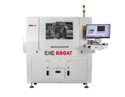
Automated depaneling equipment may use vacuum nozzles to pick up and transfer PCB assemblies. This handling function should not automatically be described as vacuum fixture hold-down. For example, the EXE 880AT uses vacuum suction for automated PCB/PCBA transfer; the actual cutting fixture and board-retention method should be defined according to the configured product and tooling.
Router depaneling removes PCB material mechanically, so the cutting process generates particulate debris. The fixture can either help or hinder the extraction system depending on how its support surfaces, cavities, openings, and air paths are designed.
If under-board extraction is used, the fixture may require local openings or channels that allow dust to move toward the extraction point without compromising PCB support. If upper extraction or a spindle brush is used, the fixture still needs sufficient clearance around the cutting region.
The objective is not simply to maximize open space. Too much open area can reduce support or change vacuum performance, while too little clearance can trap routing debris around the board.
A dedicated fixture can be optimized closely around one PCB panel, but manufacturers processing many product variants also need to consider fixture changeover time, storage, identification, maintenance, and setup verification.
| Approach | Typical Benefit | Trade-Off |
|---|---|---|
| Dedicated Fixture | Can closely match the panel geometry, support locations and component-clearance requirements. | Requires separate tooling for different products or panel revisions. |
| Adjustable / Flexible Tooling | May reduce the number of dedicated fixtures required for compatible products. | Support, locating repeatability and component clearance still need to be verified for every PCB configuration. |
Fixture requirements also depend on how PCB panels enter and leave the machine.
An offline workstation may allow an operator to load the PCB panel or fixture manually. This can make dedicated fixtures practical for high-mix production where operators regularly change products.
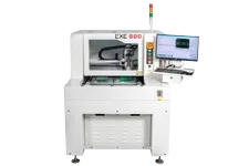
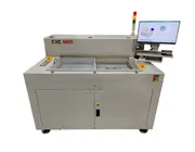
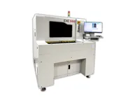
The EXE 880 Offline PCB Depaneling Machine is an example of a standalone router platform intended for flexible PCB routing workflows.
Inline systems introduce additional handling considerations because the panel, fixture and separated boards may need to work with conveyors, automatic transfer mechanisms, vacuum pickup systems or downstream production equipment.
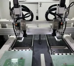
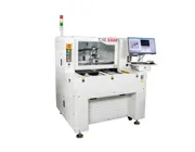
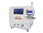
The EXE 880AT Inline PCB Depaneling Machine combines rail feeding, automated PCB transfer, CCD positioning, router cutting and configurable material output. Fixture design for this type of system should therefore be evaluated together with the complete automated handling sequence.
| Problem | Better Approach |
|---|---|
| Designing only from the PCB outline | Include component locations, component heights, routing paths and tooling-hole information. |
| Supporting only the panel rails | Consider how each individual PCB will remain supported as tabs are progressively removed. |
| Ignoring bottom-side components | Design relief pockets and non-contact zones using actual PCBA component-height information. |
| Fixture blocking the router path | Review fixture CAD against the programmed routing path and selected cutter diameter. |
| Assuming maximum vacuum is always better | Use enough retention for the validated process without unnecessarily deforming or obstructing the product. |
| Ignoring dust-extraction airflow | Evaluate support, openings and extraction paths together. |
| Optimizing fixture and cutting sequence separately | Validate fixture support and the final-tab cutting order as one process. |
Step 1 — Review the PCBA Data
Confirm panel geometry, PCB thickness, component locations, bottom-side component height, tooling holes, tabs and routing paths.
Step 2 — Define Locating Features
Determine how the panel will be repeatably positioned without interfering with components or the router path.
Step 3 — Design PCB Support and Relief Areas
Add suitable support beneath the PCB while creating clearance for components and non-contact zones.
Step 4 — Check Router and Dust-Extraction Clearance
Verify that the bit, spindle-access area and extraction structure can reach the complete programmed cutting path.
Step 5 — Review the Final-Tab Sequence
Make sure individual boards remain supported as they become progressively separated from the surrounding panel.
Step 6 — Validate With the Actual Production Cycle
Test loading, positioning, routing, dust extraction, final separation, PCB removal and product changeover before releasing the fixture for production.
Is the complete PCB panel supported in repeatable locations?
Do locating pins or nests match the actual PCB data?
Are bottom-side components protected from fixture contact?
Is there enough clearance around every router path?
Will separated PCBs remain supported after their final tabs are cut?
Can routing dust reach the extraction system?
Does vacuum performance remain sufficient as the panel is cut, if vacuum hold-down is used?
Can operators or automation load and unload the product without component interference?
Has fixture design been reviewed together with the cutting sequence?
Has the complete fixture been validated using the real production PCBA?
A PCB router fixture is tooling used to position and support a PCB or PCBA panel while a routing machine separates individual boards. It may include locating pins, nests, support surfaces, relief pockets, vacuum features or other retention structures.
Not necessarily. The required tooling depends on the PCB geometry, machine configuration, component layout and handling method. Some products use dedicated fixtures, while compatible assemblies may use adjustable or more flexible tooling.
No. Vacuum hold-down is one possible fixture strategy. Depending on the product, mechanical locating features, nests, support surfaces, lids or combinations of methods may also be used. The correct method should be validated for the actual PCB and router configuration.
Typical inputs include the panel drawing, Gerber or mechanical data, PCB dimensions, tooling-hole locations, routing paths, tab locations and top- and bottom-side component information. Component-height data is particularly important when the fixture supports a populated PCBA.
As tabs are removed, the individual PCB becomes less connected to the surrounding panel. The fixture must continue supporting the PCB so it does not shift, tilt or move into the router path when the final tab is cut.
Yes. Fixture openings, cavities, support areas and sealing can affect airflow around the cutting area. When under-board extraction or vacuum retention is used, the fixture design becomes part of the overall dust-management system.
No. Vacuum pickup normally refers to a nozzle or handling mechanism used to lift and transfer the PCB. Vacuum fixture hold-down refers to negative pressure used to retain the PCB in the cutting fixture. A machine may use one, both, or neither depending on its configuration.
A PCB depaneling fixture is not simply a tray that holds the panel. It is part of the complete routing process and should be developed together with the PCB geometry, component layout, router path, cutting sequence, dust-extraction method and loading strategy.
The strongest fixture design is therefore not the one with the most clamps or the highest vacuum level. It is the one that provides sufficient positioning and support for the actual PCBA while maintaining component clearance, router access, dust control and repeatable production handling.
Need to Evaluate a PCB Router Fixture?
Send EXE your PCB panel drawing, Gerber or mechanical data, board thickness, routing path, tab locations, tooling holes and top- and bottom-side component information. Our team can evaluate the PCB handling, fixture and router depaneling requirements for your application.
Request a PCB Depaneling Evaluation