𐄀 Focus on providing PCBA separator manufacturing process solution

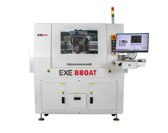
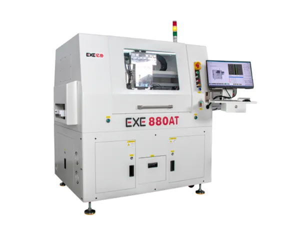
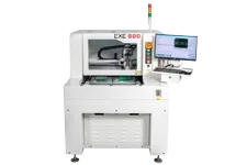
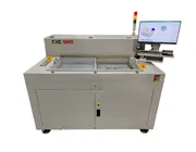
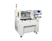
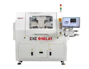
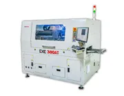
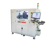
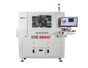
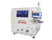
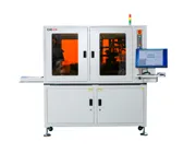
The EXE 880AT is an inline PCB depaneling machine designed for automated PCB and PCBA routing in integrated electronics production lines. It combines automatic material feeding, vacuum pick-and-place handling, CCD vision positioning, high-speed router cutting, and automatic material discharge to reduce manual handling between production processes.
With servo-controlled motion and automated PCB transfer, the EXE 880AT is suitable for manufacturers that require stable, repeatable, and highly automated PCB depaneling for continuous production.
The EXE 880AT combines high-speed PCB routing, CCD vision positioning, servo-controlled motion, automatic PCB handling, dust extraction, and flexible material transfer for inline PCB and PCBA depaneling. The specifications below summarize its cutting performance, automation functions, handling system, and machine requirements.
| Parameter | Specification |
|---|---|
| Core Cutting Performance | |
| Panel Separation Working Range | 350 × 300 mm |
| Cutting Accuracy | ±0.05 mm |
| X-Y Repeatability | ±0.02 mm |
| CCD Camera Calibration Accuracy | ±0.01 mm |
| Tool Diameter | 0.8–3.0 mm |
| Cutting Spindle | SycoTec (Germany), maximum 100,000 rpm, automatic tool change |
| Motion, Vision & Control | |
| XYZ Drive Method | AC Servo Motors |
| Number of Motion Axes | 7 Axes |
| Programming / Teaching Method | Color CCD Image-Based Intuitive Teaching Input |
| Vision System | High-Resolution Digital Camera |
| X-Y AC Servo Speed | 0–1,000 mm/s |
| Z-Axis AC Servo Speed | 0–800 mm/s |
| Drive Motor | AC Brushless Servo Motor |
| Control Method | Dedicated Controller |
| Operating Interface | Windows 7 Operating System Interface |
| Program Backup | USB Interface |
| Inline Automation & PCB Handling | |
| Feeding Method | Rail Conveyor |
| Mechanical Pick-and-Place Arm | Anti-Static Vacuum Nozzle |
| Transfer Method | Vacuum Nozzle Suction Transfer |
| Discharging Method | Belt Conveyor, Carrier Output, or Rail Conveyor |
| Flow Direction | Left → Right; Right → Left (Optional) |
| Static Elimination | Static Elimination Gun |
| Dust Extraction | |
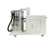
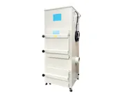
| Upper Dust Extraction Power | 5 HP |
| Lower Dust Collector Power | 3 HP (Optional 5 HP) |
| Utilities & Machine Data | |
| Main Unit & Dust Collector Voltage | 220 V, 1-Phase or 3-Phase |
| Power Consumption | 3.5 kVA |
| Dust Collection Cabinet Dimensions | 1,102 × 534 × 869 mm (D × W × H) |
| Machine Dimensions | 1,660 × 1,290 × 1,600 mm (D × W × H) |
| Main Unit + Dust Collector Weight | 1,200 kg |
The EXE 880AT integrates PCB feeding, positioning, router cutting, and material output into an automated workflow. This reduces the amount of manual PCB handling required between the depaneling process and adjacent production steps.
Step 1 — Automatic Panel Feeding
PCB or PCBA panels enter the machine through the rail conveyor as part of the inline production flow.
Step 2 — Vacuum Pickup and Transfer
The servo-controlled handling system uses an anti-static vacuum nozzle to pick up and transfer the PCB or PCBA to the cutting position.
Step 3 — CCD Vision Positioning
The high-resolution vision system supports reference recognition and positioning before the programmed routing process begins.
Step 4 — Automatic Router Cutting
The SycoTec spindle follows the programmed PCB cutting path while the dust extraction system removes routing debris from the processing area.
Step 5 — Automatic Material Output
After depaneling, the processed PCB can be transferred to a belt conveyor, carrier output, or rail conveyor according to the configured production workflow.
The EXE 880AT uses a SycoTec spindle with automatic tool-changing capability. In an automated PCB depaneling environment, automatic cutter change can reduce the need for operators to interrupt the routing process for routine tool replacement.
Router-bit selection and replacement intervals should still be determined according to PCB material, board thickness, cutting length, tool diameter, cutting parameters, and actual tool condition.
Learn more about cutter diameter, spindle speed, feed rate, and tool-life management in our PCB Router Bits for Depaneling Guide.
Inline depaneling requires more than automatic cutting. The machine must also receive PCB panels, transfer them safely through the cutting process, and deliver separated boards in a format compatible with downstream production.
| Handling Stage | EXE 880AT Configuration |
|---|---|
| Panel Feeding | Rail conveyor |
| Internal Transfer | Servo-controlled vacuum nozzle suction transfer |
| Output Options | Belt conveyor, carrier output, or rail conveyor |
| Production Flow | Left-to-right or optional right-to-left |
Both systems use router-based PCB depaneling, but they are designed for different manufacturing workflows. The EXE 880AT emphasizes automated line integration, while the EXE 880 is a flexible standalone offline system.
| Factor | EXE 880AT Inline | EXE 880 Offline |
|---|---|---|
| Production Type | Inline automated production | Standalone offline production |
| Panel Feeding | Automatic rail feeding | Operator-assisted loading |
| PCB Transfer | Automated vacuum handling | Standalone workstation workflow |
| Material Output | Automatic configurable output | Operator-assisted workflow |
| Typical Use | Automated and continuous PCB production | High-mix and flexible offline production |
If direct line integration is not required, the EXE 880 Offline PCB Depaneling Machine can provide a more flexible standalone routing solution.
Automotive Electronics
Inline depaneling can support automated production of ECU, ADAS, BMS, EV power-control, infotainment, and other automotive PCB assemblies. See our automotive PCB depaneling solutions.
Communication Electronics
Automated routing can be evaluated for 5G, RF, network, optical communication, and other communication electronics requiring repeatable PCB separation. Learn more about PCB depaneling for communication electronics.
Industrial Control Electronics
PLCs, automation controllers, power-control boards, and other industrial electronics can benefit from repeatable routing and automated material handling.
Consumer Electronics
High-volume consumer electronics production can use inline depaneling when automated PCB feeding, routing, and output are required.
EMS Manufacturing
Electronics manufacturing service providers processing multiple customer programs can evaluate the EXE 880AT where automated handling and continuous production-line integration are required.
Selecting an inline PCB depaneling machine requires evaluating both the cutting process and its connection with upstream and downstream production equipment. Conveyor height, flow direction, panel dimensions, output method, cycle-time target, and material-transfer requirements should be confirmed during project planning.
If barcode identification, MES communication, production records, customer-specific traceability, or other factory-system interfaces are required, the communication protocol and software configuration should be confirmed during equipment evaluation.
Panel Design Matters: Router channels, breakaway tabs, component clearance, fiducials, tooling holes, and fixture-support areas can all affect automated depaneling. Review our PCB Panelization Guidelines for Automated Depaneling.
An inline PCB depaneling machine integrates PCB feeding, positioning, cutting, and material output into an automated production workflow. It is designed to reduce manual handling and connect the depaneling process with upstream and downstream manufacturing equipment.
PCB panels enter through a rail conveyor. A servo-controlled vacuum handling system transfers the PCB for positioning and routing, after which the separated material can be discharged through a belt conveyor, carrier output, or rail conveyor.
Inline depaneling integrates automatic PCB handling and material flow into the production line. Offline equipment operates as a standalone workstation and is often more suitable when flexible loading, high-mix production, or direct line integration is not required.
Yes. The EXE 880AT specification includes a SycoTec spindle with automatic tool-changing capability and a maximum spindle speed of 100,000 rpm.
The EXE 880AT specifies cutting accuracy of ±0.05 mm, X-Y repeatability of ±0.02 mm, and CCD camera calibration accuracy of ±0.01 mm.
The published configuration supports belt conveyor output, carrier output, or rail conveyor output, allowing the discharge method to be selected according to the production workflow.
Useful information includes PCB material, thickness, panel dimensions, cutting drawing, routing path, component height, upstream and downstream conveyor requirements, production flow direction, target cycle time, required output method, and any traceability or factory-system integration requirements.
Evaluate an Inline PCB Depaneling Solution
Send EXE your PCB material, thickness, panel drawing, cutting path, component height, production volume, target cycle time, conveyor direction, and output requirements. Our team can help evaluate an EXE 880AT configuration for your automated PCB production line.
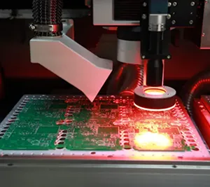
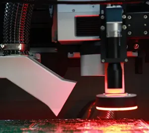
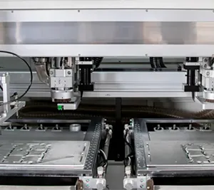
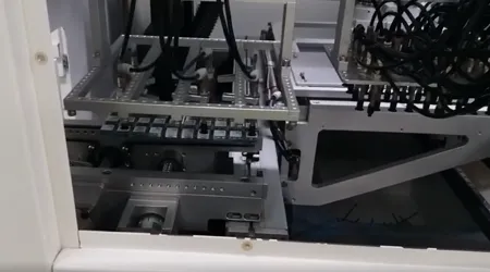
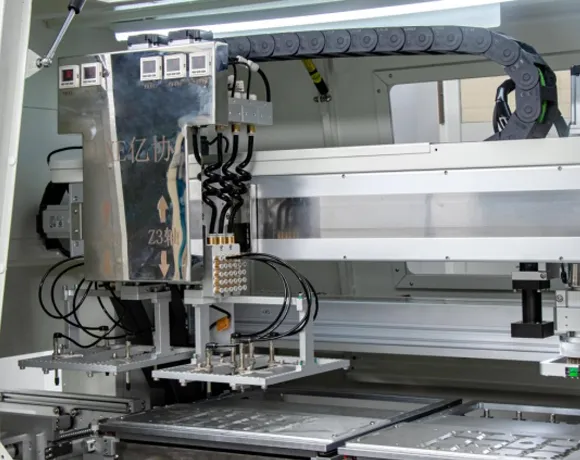
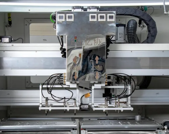
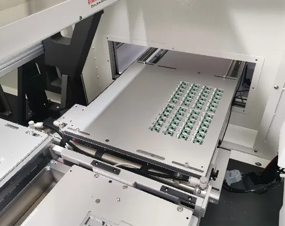
Request an Inline Depaneling EvaluationThe product separation fixture picks up the product and places it onto the processing platform for separation. After processing is complete, the fixture picks up the separated product again and places it onto the track to flow into the subsequent process.
Specialized board separation fixture rail entry method, seamlessly connecting to the preceding process.
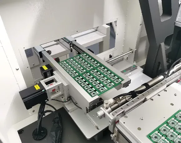
The product separation fixture picks up the product and places it onto the processing platform for separation. After processing is complete, the fixture picks up the separated product again and places it onto the conveyor track to flow into the next process step.
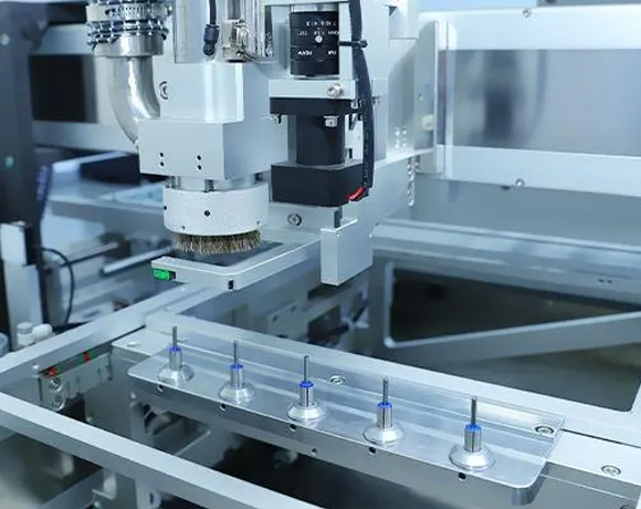
1. Equipped with an automatic tool-changing German-imported spindle. Saves time, enables automation, reduces human error, and delivers high precision and strong stability.
2. Features a built-in five-set milling cutter magazine for convenient automatic tool changes, meeting panel processing requirements.
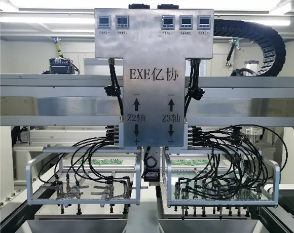
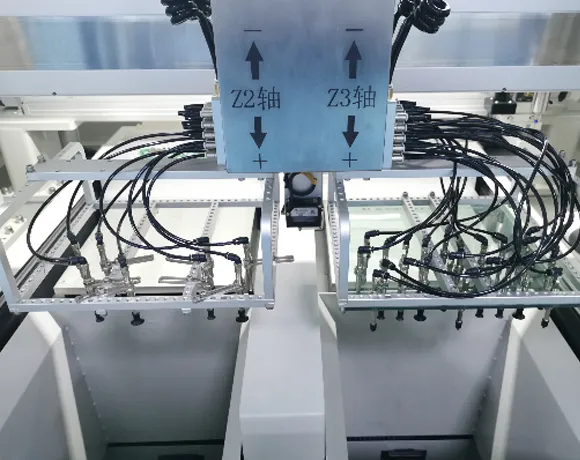
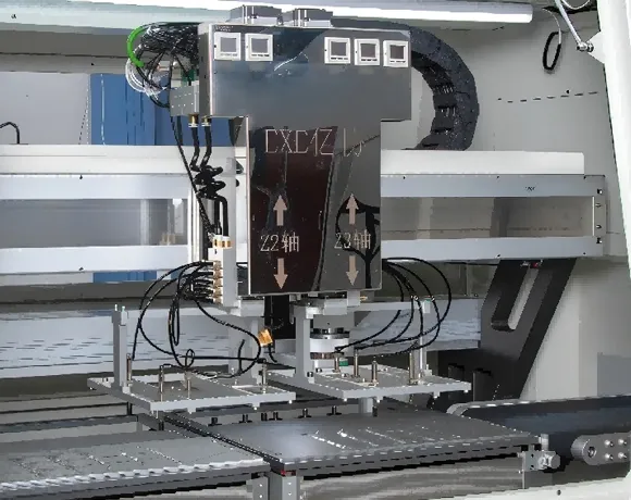
1. Handling Device: Automatic loading/unloading (modular vacuum grippers, vacuum system, independently controllable)
2. Conveying Structure: X2-axis movement, Z2/Z3-axis pickup, AC servo motor control.
3. Board Pickup Speed: 0-1000 mm/sec (adjustable)
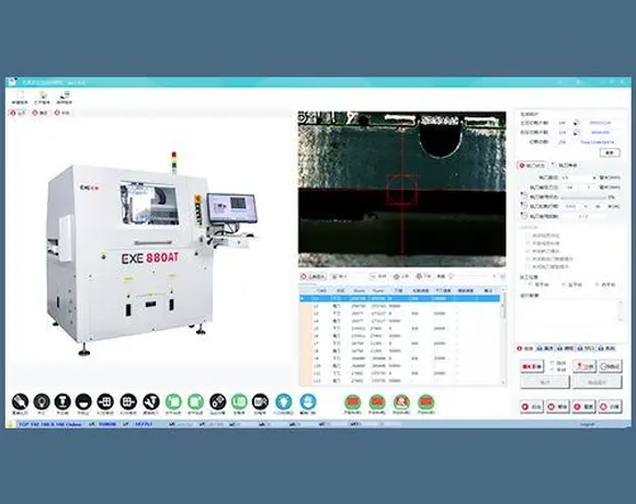
Quick Chinese-English switching on the window operating interface. The window operating interface is illustrated, the programming is simple, and multi-point program coding can be completed quickly.
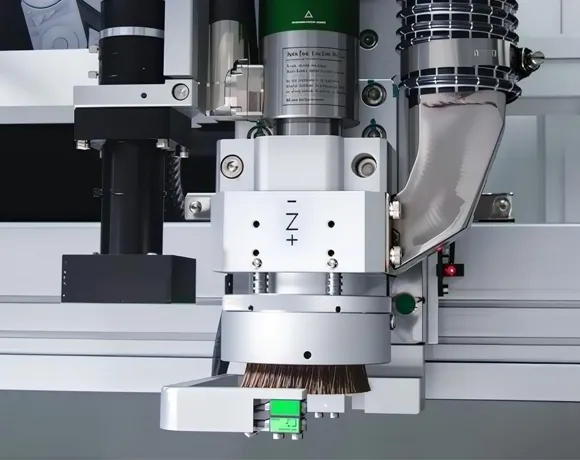
It adopts the German SycoTec spindle and an automatic tool change system, realizing fully automated tool change, saving time, reducing human factors, with high precision and strong stability.
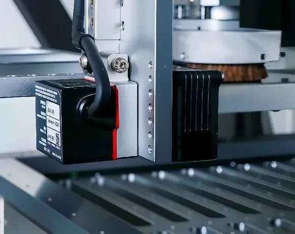
Standard PCBA product height measurement system, ensuring accurate detection during the vacuum placement of the products.
It adopts a gantry horizontal structure, which features good symmetry, high stability, and excellent rigidity.
The main structure uses a marble platform, along with motion modules and custom-cut components, ensuring high stability.
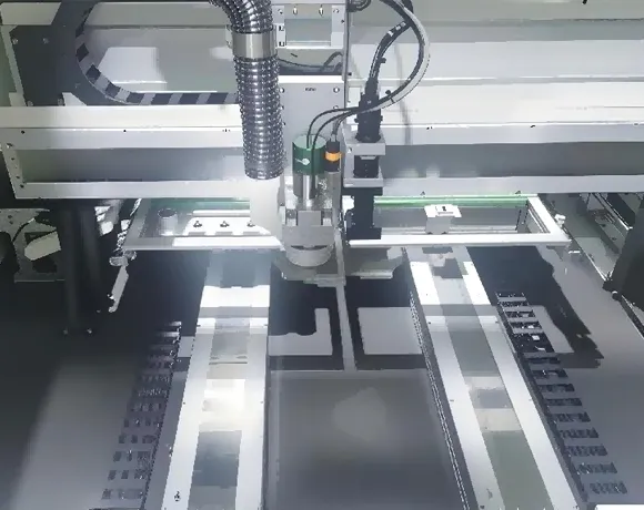
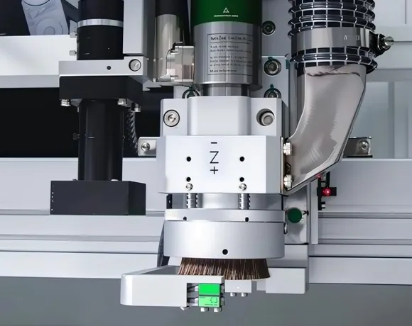
It adopts a floating brush design that automatically adjusts to achieve the optimal dust removal effect, regardless of the thickness of the board or the height of the components, thereby extending the service life of the milling cutter.
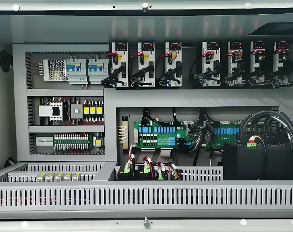
Reasonable wiring of the electrical control circuit, maintenance, easy and convenient