𐄀 Focus on providing PCBA separator manufacturing process solution

Quick Answer
A PCB depaneling machine achieves clean and precise cuts by controlling several factors at the same time: machine stability, spindle and router-bit performance, cutting-path accuracy, CCD vision alignment, fixture stability, and dust removal. In a router-based PCB depanelizer, a rigid platform helps minimize vibration, while a high-speed spindle removes PCB material with controlled mechanical force.
The vision system then corrects panel position before cutting so that the programmed routing path remains aligned with the actual PCB. When these systems work together, manufacturers can reduce burrs, cutting deviation, excessive board stress, and the risk of damage to solder joints or nearby components.
PCB depaneling is one of the final manufacturing steps before individual PCB assemblies move to testing, inspection, packaging, or final assembly. Although the cutting process may look simple, poor depaneling can introduce edge damage, excessive mechanical stress, dust contamination, or dimensional errors that affect downstream quality.
This is why modern PCB depaneling machines combine mechanical stability, motion control, vision positioning, cutting-tool management, and dust extraction rather than relying on cutting speed alone.
Below, we explain how each of these factors influences PCB cutting quality and what process engineers should check when clean, repeatable, and low-stress PCB separation is required.
Clean PCB separation depends on the entire cutting system. A high-speed spindle is important, but spindle speed alone cannot compensate for an unstable fixture, worn router bit, incorrect feed rate, poor vision calibration, or ineffective dust extraction.
| Key Factor | Why It Matters |
|---|---|
| Machine Stability | A rigid platform helps minimize vibration and provides a stable reference for high-speed routing. |
| Spindle & Router Bit | Spindle speed, tool diameter, feed rate, cutting depth, and tool wear directly affect PCB edge quality. |
| CCD Vision Alignment | Vision positioning compensates for panel loading offsets and helps align the actual PCB with the programmed cutting path. |
| Fixture & Motion Control | Stable workholding and accurate movement help maintain repeatability during complex routing paths. |
| Dust Extraction | Effective extraction removes FR4, resin, and fiberglass debris from the cutting area. |
| Process Parameters | PCB material, board thickness, routing strategy, cutting depth, and production requirements all influence the final result. |
High-speed routing creates vibration and dynamic loads. If the machine base, worktable, or fixture moves during cutting, even a small displacement can affect the relationship between the router bit and the programmed cutting path.
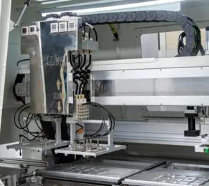
A high-rigidity marble working platform provides a stable reference surface for motion control. Its mass and structural stability help reduce vibration during rapid X-Y movement and high-speed cutting. When combined with precision ball screws, linear guides, servo control, and a correctly designed fixture, the platform helps maintain more consistent positioning during repeated production cycles.
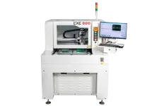
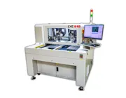
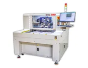
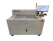
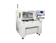
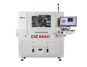
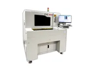
Engineering Example: The EXE 880 Offline PCB Depaneling Machine specifies X-Y repeat accuracy of ±0.02 mm, cutting accuracy of ±0.05 mm, and CCD camera calibration accuracy of ±0.01 mm. These specifications illustrate why machine structure, motion control, and vision calibration must work together as one system.
The fixture is equally important. Even a precise PCB depanelizer can produce inconsistent results if the panel is not supported correctly or if the workholding method allows the PCB to move during routing. Process engineers should therefore evaluate the machine platform and PCB fixture as a complete positioning system.
In router-based PCB depaneling, the spindle and milling cutter perform the actual material removal. Their condition and operating parameters strongly influence edge smoothness, cutting force, burr formation, and process stability.
A high-speed spindle allows the router bit to remove small amounts of material during each cutting cycle. However, higher RPM does not automatically mean better cutting quality. Spindle speed must be matched with feed rate, router-bit diameter, PCB thickness, PCB material, and cutting depth.
If feed rate is too aggressive for the selected tool and material, cutting force can increase and edge quality may deteriorate. If the parameters are too conservative, cycle time can become unnecessarily long and heat accumulation may increase. Routing parameters should therefore be validated using the actual PCB material and production conditions.
As a practical example, the EXE 880 uses an NSK spindle with a specified maximum speed of 60,000 rpm and supports router-bit diameters from 0.8 to 3.0 mm. The machine is designed for PCB thicknesses from 0.2 to 6.0 mm.
Router bits are consumable tools. As a milling cutter wears, its cutting edges become less effective, which can increase cutting force and contribute to rough PCB edges, burrs, dimensional variation, or tool breakage.
For repeatable production, a PCB depaneling machine should therefore include a clear tool-management strategy. Tool monitoring, segmented cutter-use settings, and cutting-depth compensation can help manufacturers manage cutter usage and reduce the risk of continuing production after tool failure.
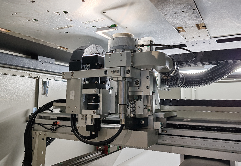
Stable motion control, high-speed routing, vision alignment, and correct cutting parameters work together to improve PCB depaneling quality.
PCB panels are not always positioned exactly where the original cutting program expects them to be. Loading variation, fixture tolerances, panel dimensional variation, and manufacturing processes can create small positional differences.
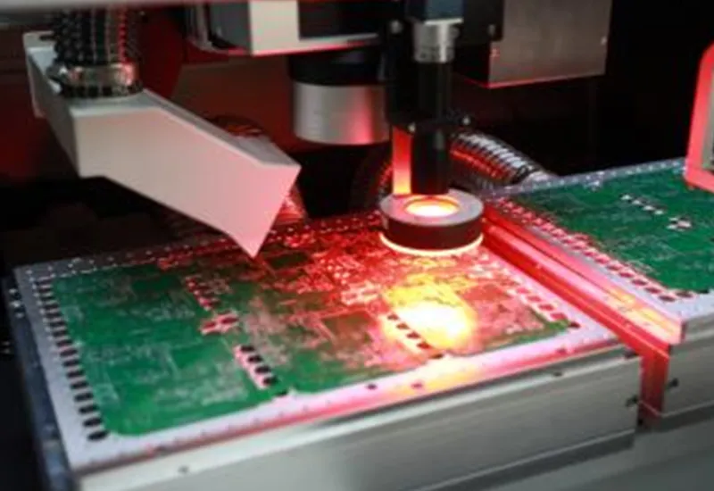
A CCD vision system helps compensate for these differences before routing begins. Instead of assuming that every panel is in an identical position, the machine identifies reference marks and calculates the relationship between the actual panel and the programmed coordinate system.
Step 1 — Detect PCB Fiducial or Mark Points: The CCD camera identifies predefined reference features on the PCB panel.
Step 2 — Calculate Actual Panel Coordinates: The vision system determines the real position of the loaded PCB relative to the machine coordinate system.
Step 3 — Compare with the Programmed Cutting Path: Software compares the detected PCB position with the original routing program.
Step 4 — Apply Position Compensation: The cutting path is corrected before routing so that the tool follows the intended separation path more accurately.
This process is particularly important for densely populated PCB assemblies where the distance between the cutting path and nearby components is limited. CCD alignment helps reduce positioning error and improves cutting-path consistency for automotive electronics, medical devices, communication modules, and other high-density PCB assemblies.
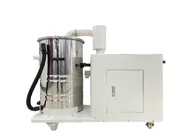
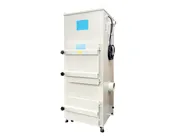
Mechanical routing removes material from the PCB, producing dust and small particles from materials such as FR4, resin, and fiberglass. If this debris is not removed effectively, it can accumulate around the cutting area, fixture, optical components, and machine transmission system.
Effective dust extraction therefore contributes to both product cleanliness and equipment stability. The extraction system should collect debris close to the cutting point while maintaining sufficient airflow throughout the routing process.
Depending on the production environment, manufacturers can evaluate upper dust collection and lower dust collection solutions as part of the complete PCB routing process.
Process Tip: If PCB edge quality is acceptable but dust contamination remains high, increasing spindle speed alone will not solve the problem. Check extraction airflow, suction-point position, filter condition, fixture design, and whether debris can escape from the cutting enclosure.
Mechanical accuracy is only part of the process. Operators and engineers also need software that makes program creation, parameter control, recipe management, and production changeovers repeatable.
A practical control system should allow engineers to define cutting paths and process parameters while restricting unauthorized changes to critical settings. Multi-level user permissions are useful because spindle settings, cutting depth, tool compensation, and motion parameters should not be changed accidentally during daily production.
On dual-worktable machines, software and safety systems can also coordinate loading and cutting operations. One worktable can be used for processing while the other is prepared for the next panel, helping reduce non-cutting time. Safety light curtains and interlocks help separate operator activity from machine motion.
When PCB depaneling quality begins to deteriorate, the visible defect is usually only the symptom. Process engineers should check the cutting tool, machine alignment, fixture, process parameters, and extraction system before changing a single setting in isolation.
| PCB Depaneling Problem | Possible Cause | Recommended Check |
|---|---|---|
| Burrs on PCB edges | Worn router bit, unsuitable speed/feed combination, or incorrect cutting depth | Inspect tool wear and verify routing parameters |
| Rough cutting edge | Tool wear, spindle instability, fixture movement, or unsuitable feed rate | Check spindle condition, cutter condition, and PCB support |
| Cutting-path deviation | Incorrect CCD calibration, fixture movement, or panel positioning variation | Recheck fiducial recognition, calibration, and fixture repeatability |
| Excessive board stress | High cutting force, worn cutter, unsupported PCB area, or unsuitable routing strategy | Review cutter condition, support points, cutting sequence, and process settings |
| Excessive PCB dust | Insufficient extraction airflow or poor suction-point positioning | Inspect dust collector, filters, hoses, seals, and extraction position |
| Router-bit breakage | Incorrect cutting depth, excessive feed rate, tool wear, or improper tool selection | Review tool diameter, cutting depth, PCB material, and tool life |
Router and laser depaneling can both achieve high-quality PCB separation, but they use fundamentally different cutting methods. The best option depends on PCB material, board thickness, component sensitivity, required accuracy, dust requirements, cycle time, production volume, and cost targets.
| Factor | Router PCB Depaneling | Laser PCB Depaneling |
|---|---|---|
| Cutting Principle | Mechanical material removal with a rotating milling cutter | Non-contact laser cutting |
| Mechanical Stress | Low when tooling, fixture, and process parameters are correctly controlled | Very low because there is no mechanical cutting tool contacting the PCB |
| Cutting Debris | Produces routing dust that requires extraction | No router-bit dust, although fumes and particles still require suitable extraction |
| Tool Wear | Router bits are consumables and require tool-life management | No mechanical router bit |
| Complex Contours | Suitable for straight and irregular routing paths | Well suited to complex and high-precision cutting paths |
| Typical Applications | General PCBA production, wider thickness ranges, flexible routing applications | High-density boards, thin materials, precision applications, and very low-stress requirements |
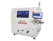
For example, the EXE 960 Offline Laser Depaneling Machine uses a non-contact laser process and specifies cutting precision of ±20 μm, repeatability of ±2 μm, and X/Y/Z resolution of 1 μm.
Neither technology is universally better. The correct choice depends on the actual PCB structure, material, component sensitivity, production volume, quality requirements, and total manufacturing process.
Technical specifications provide more useful information than generic claims such as “high precision.” The following values provide a practical example of the parameters engineers can compare when evaluating a PCB depanelizer.
| Parameter | EXE 880 Specification | Why It Matters |
|---|---|---|
| X-Y repeat accuracy | ±0.02 mm | Indicates how consistently the motion system returns to programmed positions |
| Cutting accuracy | ±0.05 mm | Important when routing paths are close to components or board features |
| CCD calibration accuracy | ±0.01 mm | Supports more accurate vision-based positioning and compensation |
| Board separation stress | <300 μɛ | Helps evaluate mechanical stress during PCB separation |
| NSK spindle speed | Max. 60,000 rpm | Supports high-speed mechanical PCB routing |
| Router-bit diameter | 0.8–3.0 mm | Allows tool selection according to routing path requirements |
| PCB cutting thickness | 0.2–6.0 mm | Defines the supported PCB thickness range |
When comparing PCB depaneling equipment, do not evaluate a machine based only on maximum spindle speed or advertised accuracy. The machine should be assessed against the actual product and production process.
Important factors include:
PCB material and board thickness
Panel dimensions and PCB layout
Distance between components and the cutting path
Maximum acceptable board stress
Required production cycle time
Product mix and changeover frequency
Dust-control and cleanliness requirements
Fixture design
Offline or inline automation requirements
Selection Tip: For high-mix manufacturing, flexibility, fast program changeover, vision correction, and fixture compatibility may be especially important. For high-volume production, automation, loading and unloading efficiency, traceability, repeatability, and integration with upstream and downstream equipment often become more important.
A sample PCB and production requirement should therefore be reviewed before final machine selection. This allows cutting method, tooling, fixture design, cycle time, dust extraction, and automation requirements to be evaluated together rather than separately.
A PCB depaneling machine separates individual printed circuit boards or PCB assemblies from a larger production panel. Depending on the application, depaneling can use routing, laser cutting, sawing, V-cut separation, or other methods. Automated machines help improve cutting consistency, control mechanical stress, and increase production efficiency.
In a router-based PCB depaneling machine, the PCB panel is held in a fixture while a high-speed spindle and milling cutter follow a programmed cutting path. A CCD vision system can detect PCB reference marks and compensate for positional variation before cutting. Dust extraction removes debris generated during routing.
Burrs can be caused by worn router bits, unsuitable spindle speed or feed rate, incorrect cutting depth, inadequate PCB support, tool runout, or material-specific cutting conditions. Tool condition and process parameters should be checked together when edge quality begins to deteriorate.
Mechanical stress can be reduced through stable PCB support, appropriate routing parameters, sharp cutting tools, optimized cutting sequences, accurate motion control, and low-force separation methods. Sensitive assemblies may also benefit from non-contact laser depaneling when the application requires very low mechanical stress.
The correct spindle speed depends on PCB material, router-bit diameter, cutting depth, feed rate, and machine configuration. For example, the EXE 880 uses an NSK spindle with a specified maximum speed of 60,000 rpm. Process parameters should always be validated for the actual PCB rather than selected by RPM alone.
Not necessarily. Router depaneling is flexible and suitable for many FR4 PCB applications and board thicknesses, while laser depaneling offers non-contact cutting with very low mechanical stress and high precision. The better solution depends on PCB material, thickness, component sensitivity, production volume, contamination requirements, and cost targets.
CCD vision detects reference marks on the PCB and allows the machine to compare the actual board position with the programmed cutting path. Position compensation helps reduce cutting deviation caused by loading offsets, panel variation, or fixture tolerances.
Clean and precise PCB depaneling is not produced by one component alone. Machine rigidity, spindle performance, router-bit condition, PCB support, CCD alignment, motion accuracy, process parameters, and dust extraction all influence the final cutting result.
For router-based production, a stable platform and properly controlled high-speed spindle help reduce cutting variation and mechanical stress. Vision positioning improves cutting-path alignment, while tool monitoring and dust extraction support more consistent long-term production. For extremely sensitive or high-precision applications, laser PCB depaneling provides an alternative non-contact process.
EXE provides offline, inline, router, and laser PCB depaneling solutions for different PCB materials, product structures, production volumes, and automation requirements. The correct machine should always be selected based on the actual PCB and manufacturing process rather than a single specification.
Need Help Selecting a PCB Depaneling Solution?
Send EXE your PCB size, material, thickness, panel drawing, cycle-time requirement, and production method. Our team can help evaluate the suitable cutting process and machine configuration for your application.
Contact EXE