𐄀 Focus on providing PCBA separator manufacturing process solution

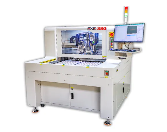
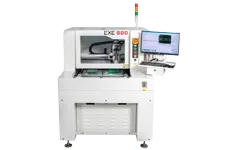
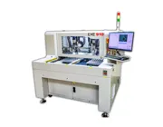
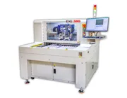
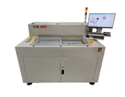
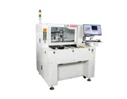
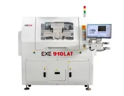
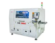
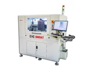
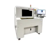
The EXE 380 Offline PCB Milling & Sawing Depaneling Machine combines a milling cutter and toothed saw blade in one standalone PCB separation system. It is designed for production environments that need to process both V-groove panels and stamp-hole panel structures without relying on a single cutting method.
The saw-blade axis can rotate 90° to support X/Y-direction V-groove cutting, while the milling process provides an alternative cutting method for suitable panel structures. Dual Y-axis worktables, CCD Mark positioning, a marble platform, and upper/lower dust extraction support stable offline PCB depaneling and flexible production changeovers.
The EXE 380 is an offline PCB depaneling platform that combines a toothed saw blade and milling cutter within one machine. The technical parameters below describe the current standard machine configuration and should be evaluated together with the actual PCB panel structure and cutting requirements.
| PCB Processing Range | |
| Panel Cutting Dimensions | 350 × 450 mm |
| Panel Cutting Thickness | 0.4–3.6 mm |
| Panel Cutting Speed | 0–200 mm/s |
| Cutting Method | Toothed Saw Blade + Milling Cutter |
| Cutting, Positioning & Worktable | |
| Accuracy Control | CCD Camera Positioning + Mark Calibration |
| Cutting Motor Power | 500 W |
| Cutting Motor Speed | 13,000 rpm |
| Number of Work Platforms | 2 |
| Rotational Cutting Feature | Rotating cutting-head structure for multi-direction cutting |
| Dust Extraction & Machine Data | |
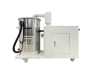
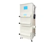
| Dust Removal Method | Upper / Lower Dust Removal |
| Power Supply | 220 V, 4 kW |
| Equipment Dimensions | L1065 × W1065 × H1520 |
One Machine, Two Mechanical Cutting Processes
The reason to select the EXE 380 is not simply that it is another offline PCB depaneling machine. Its key distinction is the integration of milling and sawing within the same equipment platform.
This configuration can be evaluated when a manufacturer's PCB portfolio contains different separation structures, such as suitable V-groove panels and panel designs requiring milling-based separation. The process should be selected according to the actual panel rather than forcing every PCB through the same cutting method.
Milling and sawing are both mechanical PCB separation processes, but they should not be treated as interchangeable. The panel geometry determines which process is appropriate.
PROCESS A
Milling Cutter
Milling removes PCB material along the programmed cutting area and can be considered for panel structures where a milling-based separation path is required.
On the EXE 380, this capability complements the saw-blade process so manufacturers are not limited to one mechanical separation method.
PROCESS B
Toothed Saw Blade
Sawing is intended for suitable straight separation paths such as V-groove panel structures. The cutting-head rotation also allows the machine to address different cutting directions.
The final process must still be confirmed from the V-groove geometry, PCB thickness, component clearance and required cutting quality.
Some PCB panels contain V-groove separation lines in more than one direction. The EXE 380 uses a rotating saw-axis structure so the cutting orientation can be changed instead of requiring every V-groove to run in only one machine direction.
X-Direction
Process suitable V-groove lines in one panel direction
Rotating Axis
Changes cutting orientation for the configured panel
Y-Direction
Process suitable V-groove lines in the second direction
Process Note: A rotating saw axis does not mean every PCB contour can be processed by sawing. Sawing is still intended for suitable cutting-line geometry. Irregular or localized separation areas should be evaluated for the milling process or another depaneling method.
The EXE 380 is most useful when process selection starts from the PCB panel itself. The table below is a practical way to separate the two cutting roles.
| Panel / Cutting Condition | Milling | Sawing |
|---|---|---|
| V-Groove Separation | Not the main reason to select the milling process | Primary application for suitable straight V-groove cutting |
| Stamp-Hole Panel Structure | Can be evaluated for suitable milling-based separation | Depends on whether the panel contains a suitable saw-cut path |
| X/Y V-Groove Directions | Evaluate according to the programmed milling path | Rotating cutting-axis structure supports multi-direction V-groove processing |
| Irregular Local Separation | Milling should be evaluated from the actual cutting drawing | Generally requires a suitable straight saw-cut path |
| Dust Extraction | Mechanical cutting debris requires extraction | Mechanical cutting debris requires extraction |
The EXE 380 should be presented as an offline combined-cutting platform. Its core configuration is built around cutting flexibility, dual worktables, visual positioning and mechanical dust control rather than inline rail feeding or automatic downstream transfer.
Combined Milling & Sawing Module
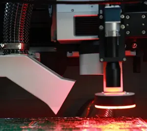
A toothed saw blade and milling cutter are integrated within the same machine so the cutting process can be selected according to suitable PCB panel structures.
Rotating Cutting-Axis Structure
The rotating cutting structure supports different cutting orientations for suitable V-groove panel layouts.
Dual Work Platforms
Two work platforms support an offline production workflow and allow operators to organize loading, cutting and product changeover more flexibly.
CCD Camera Positioning
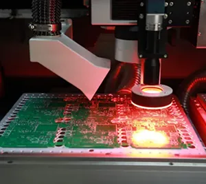
CCD camera positioning and Mark calibration help align the actual panel with the configured cutting position.
Upper & Lower Dust Removal
Upper and lower extraction structures are used to help remove debris generated during mechanical PCB milling and sawing.
Both machines are offline PCB depaneling systems, but they should not be positioned as substitutes with different model numbers. Their cutting architectures address different process requirements.
| Decision Factor | EXE 380 | EXE 880 |
|---|---|---|
| Production Mode | Offline | Offline |
| Main Cutting Architecture | Toothed saw blade + milling cutter | High-speed router milling |
| V-Groove Sawing | Integrated saw-blade process for suitable V-groove panels | Not the primary cutting process |
| Main Selection Reason | A production mix that benefits from combined milling and sawing | Dedicated router depaneling with flexible programmed routing paths |
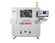
If the PCB application primarily requires high-speed router milling rather than combined sawing and milling, review the EXE 880 Offline PCB Depaneling Machine.
The EXE 380 and EXE 380AT belong to the same product family, but their current configurations address different manufacturing workflows.
| Factor | EXE 380 Offline | EXE 380AT Online |
|---|---|---|
| Production Layout | Standalone offline workflow | Inline automated workflow |
| Published Cutting Method | Toothed blade + milling cutter | Toothed blade |
| Automatic Rail Feeding | Not part of the current offline positioning | Yes |
| Automatic Discharge / Clamping | Offline handling workflow | Rail-type discharge and automatic clamping |
| Best Evaluated For | Flexible standalone production requiring combined cutting capability | Automated V-groove sawing integrated into a production line |
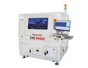
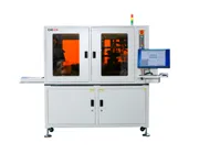
For automatic rail feeding, material discharge and inline handling, see the EXE 380AT Online Integrated Sawing Depaneling Machine.
Your factory processes V-groove panels
The integrated saw-blade process can be evaluated for suitable straight V-groove separation, including panel designs containing different cutting directions.
Your product mix includes more than one separation structure
The combination of milling and sawing provides another process option when different PCB models cannot all be handled efficiently by one cutting approach.
You need a standalone rather than inline machine
The offline architecture and dual work platforms are better aligned with production environments where operators manage loading, product changeovers and multiple PCB models outside a continuously connected line.
Mechanical cutting debris must be controlled
The machine's upper and lower dust-removal configuration supports debris extraction during the milling and sawing process.
Panel design affects process selection. Before confirming milling or sawing, review the V-score direction, separation structure, tooling holes, component clearance and available cutting path. See our PCB Panelization Design for Automated Depaneling for additional DFM considerations.
A machine should not be selected from the model name alone. For the EXE 380, EXE recommends reviewing the actual panel before confirming whether milling, sawing, or another depaneling process is more appropriate.
Send these files and production details for a trial-cut evaluation:
✓ PCB / PCBA panel drawing
✓ Panel dimensions and thickness
✓ V-groove location and direction
✓ Stamp-hole or other separation structure
✓ Top and bottom component positions
✓ Components close to the cutting line
✓ Required production cycle time
✓ Required cutting-edge quality
If you are still comparing milling, laser, V-cut, punching and other PCB separation processes, read the PCB Depaneling Methods Comparison.
Milling removes PCB material with a rotating milling cutter along the configured cutting path, while sawing uses a toothed blade and is intended for suitable straight cutting lines such as V-groove separation. The appropriate process depends on the actual panel structure.
The EXE 380 uses a rotating cutting-axis structure for different cutting orientations. The actual V-groove layout, component clearance and cutting sequence should be reviewed before the production process is confirmed.
The EXE 380 is an offline machine with a published toothed-blade and milling-cutter configuration. The EXE 380AT is designed for inline production and adds automatic rail feeding, discharge and clamping to its sawing workflow.
Consider the EXE 380 when combined milling and saw-blade processing is relevant to your PCB panel mix. If the main requirement is flexible router milling rather than V-groove sawing, the EXE 880 is usually the more relevant machine to evaluate.
Not Sure Whether Your Panel Should Be Milled or Sawed?
Send EXE your PCB panel drawing, board thickness, V-groove or stamp-hole structure, component-clearance information and production requirements. We can evaluate whether the EXE 380 combined milling-and-sawing process is appropriate before machine selection.
Send Your PCB for Process EvaluationGantry Horizontal Module
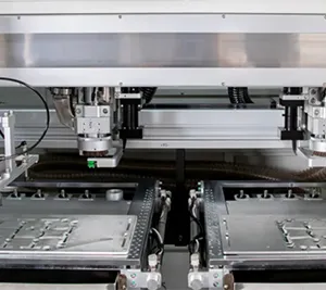
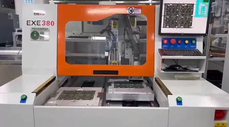
The gantry-style horizontal structure provides a stable mechanical platform for the cutting and positioning system during offline PCB depaneling.
Dual Work Platforms
Two work platforms support alternating loading and processing in an offline production workflow.
CCD Camera Positioning
CCD camera positioning and Mark calibration help align the PCB panel with the configured cutting position.
Milling & Sawing Cutting Module
The machine integrates a toothed saw blade and milling cutter so different suitable PCB panel structures can be evaluated with different mechanical cutting methods.