𐄀 Focus on providing PCBA separator manufacturing process solution

The dust collector is running — so why is routing dust still left around the PCB?
In PCB router depaneling, poor dust removal is not always caused by an undersized dust collector. The actual problem may be the distance between the cutter and suction point, blocked fixture airflow, a loaded filter, duct resistance, air leakage, router-bit wear, or a cutting condition that produces more debris than the original process.
PCB depaneling dust extraction should therefore be treated as a complete system rather than a single machine specification. Effective extraction depends on how dust is generated, where it travels immediately after cutting, how close the capture point is to the source, and whether the airflow path remains effective throughout production.
This guide focuses on diagnosing practical PCB router dust problems and identifying what should be checked before simply increasing dust collector power.
The location and timing of the remaining dust can provide useful clues. Use the symptoms below as a starting point rather than assuming the dust collector itself is the only cause.
| What You See | Possible Cause | Check First |
|---|---|---|
| Dust remains directly beside the routed edge | The capture point may be too far from the cutter or poorly positioned. | Brush, hood, nozzle or lower suction opening around the active cutting area. |
| Dust collects inside fixture pockets | Fixture cavities may create low-airflow or dead zones. | Fixture openings, channels, sealing and suction location. |
| Suction is good after maintenance but becomes weak later | Filters, dust bags or ducts may be loading with debris. | Filter condition, waste level, hoses and system resistance. |
| One side of the PCB is cleaner than the other | Airflow or capture geometry may be uneven across the routing path. | Cutting direction, fixture geometry and local suction distribution. |
| Dust suddenly increases on a previously stable product | Router-bit wear, parameter changes, material changes or extraction deterioration. | Tool condition and process history before changing collector settings. |
| Machine interior gradually becomes dusty | Particles are escaping the local capture zone during each cycle. | Capture efficiency at the source rather than only total collector airflow. |
A useful way to troubleshoot PCB depaneling dust is to follow the complete path from the router bit to the collection container.
General local exhaust ventilation engineering follows the same principle: understand where a contaminant is generated and capture it close to its source. The UK Health and Safety Executive guidance on local exhaust ventilation emphasizes understanding the process and source before designing the extraction system.
“FR4 dust” should not be treated as one perfectly uniform material. FR-4 describes a class of flame-retardant glass-reinforced laminate systems, and the exact PCB construction varies among laminate suppliers, stackups and finished boards.
For example, Isola's FR408HR material documentation describes the laminate as a resin system reinforced with electrical-grade E-glass fabric. During routing, debris may therefore include particles originating from the resin and glass reinforcement, together with material from other layers encountered by the cutter.
Do not assume all PCB dust behaves the same way. Board material, copper distribution, coatings, cutter geometry and cutting parameters can all change the amount and character of debris generated during depaneling.
One of the first places to investigate is the physical relationship between the cutting point and the dust inlet.
Fine particles can follow local air movement instead of simply falling straight downward. The HSE's broader LEV guidance notes that smaller airborne particles can remain suspended and move with air currents, which is one reason effective capture should occur near the source rather than after contaminants have dispersed.
Check these points before increasing suction power:
Capture distance: Is the brush, hood or lower suction opening actually close to the active cutting point?
Spindle movement: Does the capture structure remain effective across the complete routing path?
Component clearance: Are tall components forcing the extraction structure too far away from the PCB?
Debris direction: Does the current hood or suction inlet intercept the direction in which material is actually being ejected?
Lower dust extraction is highly dependent on what is underneath the PCB. Even with strong suction at the dust collector, very little useful airflow may reach the router bit if the fixture blocks the path between the cutting point and the extraction inlet.
The opposite mistake is also possible. Removing too much fixture material to create airflow can reduce PCB support and allow the board to move or flex during routing.
| Fixture Observation | What It May Indicate |
|---|---|
| Dust concentrated inside deep cavities | Airflow may not be sweeping the cavity effectively. |
| Good suction near one tab but weak suction near another | Fixture openings may not follow the complete routing path. |
| Vacuum changes after several PCBs are separated | Cutting may be changing the sealing or airflow conditions of the fixture. |
Fixture support and dust extraction should therefore be evaluated as one process. The best fixture is not simply the one with the largest vacuum openings; it must provide both stable PCB support and an effective extraction path.
Hearing the collector motor run does not confirm that the required airflow is still reaching the PCB.
Dust loading increases resistance through filters and collection media. Duct contamination, damaged hoses, leakage, partially blocked ports, or loose connections can also reduce the useful suction available at the cutting point.
HSE guidance for local exhaust ventilation also stresses that effective systems require proper design, commissioning, testing and ongoing maintenance rather than simply installing an extraction fan. HSG258 provides a detailed overview of LEV design and maintenance principles.
If dust suddenly becomes worse while the extraction system itself has not changed, the cutting process should also be investigated.
Worn Router Bit
Tool wear can change cutting force, vibration, edge quality and the way material is removed from the PCB.
Different Router Bit Diameter
Changing the tool can change the amount of material removed and may also change the available clearance around the extraction structure.
Feed Rate or Spindle Changes
A different cutting recipe can change cutting load, chip formation and debris behavior.
Different PCB Material
A new laminate or board stackup may not produce debris in exactly the same way as the previous product.
Before changing the extraction system, compare tool condition and cutting parameters with the last known stable production condition. Our PCB Router Bits for Depaneling Guide explains how cutter diameter, RPM, feed rate and tool condition interact during PCB routing.
Upper and lower extraction should not be treated as a simple “better vs. worse” comparison. Each captures dust from a different position around the PCB.
Consider upper extraction when:
• Capture can be positioned close to the spindle and cutting point.
• PCB component height allows the brush or extraction hood to move safely.
• Debris tends to remain around the upper cutting area.
Consider lower extraction when:
• The fixture can provide a direct airflow path beneath the routing region.
• Under-board collection can be integrated without sacrificing PCB support.
• The machine structure is designed to capture debris below the cutting area.
Some applications may use upper and lower extraction together, but adding another suction source does not automatically solve an airflow problem. Both extraction paths still need to be properly configured and maintained.
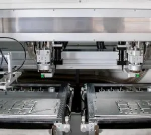
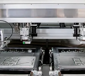
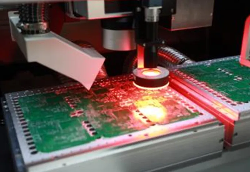
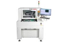
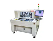
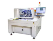
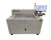
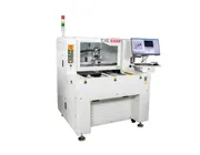
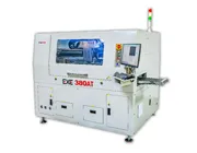
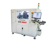
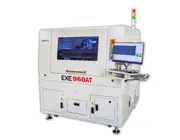
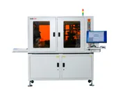
The EXE 880 Offline PCB Depaneling Machine provides a useful example of how dust extraction is integrated into the routing process rather than treated as a separate accessory.
Its published configuration includes a sealed lower dust-collection structure with an angled suction inlet. An optional upper dust-collection mechanism uses a brush structure around the cutting point. The objective of these structures is to improve capture close to the router process while accommodating the PCB and cutting path.
Need the dust collector specifications?
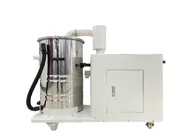
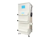
Technical specifications such as power, inlet air volume, wind speed, inlet diameter and cabinet dimensions are available on the EXE Upper Dust Collector and EXE Lower Dust Collector pages.
Horsepower tells you something about the motor. It does not, by itself, tell you how much useful airflow reaches a router bit inside a PCB depaneling machine.
Two systems with different motor ratings may also have different inlet sizes, duct geometries, filter configurations, static-pressure characteristics and intended applications. This is why dust collector comparison should include the complete system rather than ranking machines by HP alone.
A fixed maintenance interval can be useful, but production conditions vary too much to rely only on calendar-based cleaning. Routing volume, PCB material, cutting length and filter capacity all affect how quickly the system loads with dust.
In addition to the equipment manufacturer's scheduled maintenance requirements, these operating changes should trigger an inspection:
Dust becomes more visible: inspect the local capture point and filter condition.
Suction sound or airflow changes: inspect hoses, filters and possible restrictions.
A new PCB product is introduced: confirm that the existing fixture and extraction path still work for the new routing geometry.
Router parameters are changed: observe whether debris behavior changes during qualification.
Dust accumulates in unexpected locations: look for new airflow dead zones rather than only cleaning the visible debris.
PCB dust should not simply be allowed to disperse into the working environment. Actual occupational exposure requirements depend on the PCB materials being processed, local regulations, safety data sheets, extraction configuration and workplace risk assessment.
For background on fibrous glass exposure, NIOSH provides occupational-health information on fibrous glass . This does not establish a PCB-specific exposure limit, but it reinforces why dust-generation processes should use appropriate engineering controls and workplace safety procedures.
What about laser depaneling?
Laser depaneling does not generate router-bit cutting debris, but non-contact laser ablation can produce fumes and fine particulate that require a different extraction strategy.
For a process-level comparison, see our PCB Depaneling Methods Comparison .
The problem may be poor source capture, fixture airflow restrictions, loaded filters, blocked ducts, leakage or changes in the routing process. Collector operation alone does not confirm effective airflow at the cutter.
Neither is universally better. The appropriate arrangement depends on spindle position, fixture design, PCB geometry, component height, routing path and the direction in which debris travels during cutting.
Yes. Fixture support surfaces, cavities, openings and sealing can significantly affect whether useful airflow reaches the cutting point, especially with lower extraction.
No. Motor power is only one specification. Airflow at the cutting point, inlet size, system resistance, filter loading, duct configuration and capture geometry must also be considered.
The key takeaway
If PCB routing dust remains after depaneling, do not immediately assume that the solution is a larger dust collector.
Start at the router bit and follow the complete dust path: cutting condition → capture point → fixture → duct → filter → collector. Finding where that chain stops working is usually more useful than changing one specification in isolation.
Still Finding Dust Around the PCB After Routing?
Send EXE your PCB material, routing path, board thickness, fixture structure, current depaneling machine configuration and photos or video of where dust remains. This information can help identify whether the issue is related to cutting, source capture, fixture airflow or the dust-collection system.
Discuss Your PCB Dust Problem