𐄀 Focus on providing PCBA separator manufacturing process solution


PCB Depaneling for Communication & 5G Electronics
Communication and 5G electronics often use high-density PCB layouts, RF components, multilayer boards, optical communication modules, and tightly controlled mechanical structures. During depaneling, excessive mechanical stress, poor edge quality, positioning errors, or routing debris may introduce additional manufacturing risks.
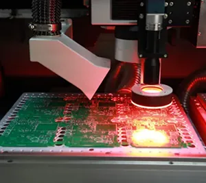
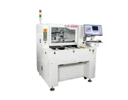
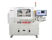
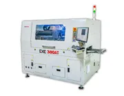
EXE provides PCB depaneling solutions for communication electronics using router and laser technologies. Depending on PCB material, thickness, component clearance, production volume, and accuracy requirements, manufacturers can select offline or inline depaneling systems for applications such as 5G base stations, optical communication equipment, routers, switches, and RF modules.
Communication electronics place demanding requirements on PCB manufacturing. The depaneling process must balance cutting accuracy, mechanical stress, dust control, fixture stability, and production efficiency without introducing unnecessary risk to high-value assemblies.
1. High-Density RF and Communication PCB Layouts
5G base stations, optical communication equipment, routers, switches, and RF modules may use densely populated PCBs with BGAs, RF connectors, shielding structures, power components, and other devices positioned close to the board edge. Accurate routing and stable PCB positioning become increasingly important as component clearance decreases.
2. Multilayer, Thick-Copper and Specialty PCB Structures
Communication equipment may use multilayer boards, thick-copper PCBs, metal-based structures, or high-frequency materials. These substrates can behave differently during routing, so cutter selection, spindle speed, feed rate, cutting depth, fixture design, and dust extraction should be validated for the actual PCB material.
3. Cutting Accuracy and Mechanical Stress
Poor edge quality, excessive board flex, unstable fixturing, or cutting-path deviation may increase the risk of PCB damage or stress being transferred to nearby solder joints and components. Stable motion control, accurate vision alignment, and appropriate routing parameters help improve cutting consistency.
4. Dust Control and Batch-to-Batch Consistency
PCB routing generates FR4, resin, fiberglass, and other cutting debris. At the same time, router-bit wear can gradually change cutting performance. Effective dust extraction, cutter monitoring, process-parameter control, and repeatable fixtures help maintain more consistent production over long batches.
When selecting a PCB depaneling machine for communication electronics, process engineers should evaluate the complete cutting process rather than focusing on a single accuracy or speed specification.
| Requirement | Why It Matters |
|---|---|
| Low Mechanical Stress | Helps reduce PCB flex and mechanical force transferred to solder joints, connectors, and sensitive components. |
| Accurate Cutting Path | Important for dense RF layouts, shielding structures, and components positioned close to the PCB edge. |
| CCD Vision Alignment | Compensates for PCB loading offsets, panel variation, and fixture tolerances before routing. |
| Stable PCB Fixturing | Helps reduce board movement and vibration during high-speed cutting. |
| Router-Bit Management | Cutter monitoring and tool-life management help reduce cutting-quality changes caused by worn or damaged tools. |
| Dust Extraction | Removes routing debris from the cutting area and helps maintain PCB, fixture, and machine cleanliness. |
| Process Repeatability | Supports more consistent cutting performance across repeated production batches. |
| Production-Line Integration | Inline loading, barcode recognition, MES connectivity, and automated handling may be important for high-volume communication electronics production. |
PCB depaneling equipment can be used across a wide range of communication and network electronics. The actual machine configuration should be selected according to board size, PCB material, component layout, production volume, and automation requirements.
| Application | Typical PCB Assemblies |
|---|---|
| 5G / 6G Base Stations | AAU RF boards, BBU baseband boards, control boards, clock boards, power boards, and related communication modules. |
| Optical Communication Equipment | Optical module PCBs, optical transport equipment boards, PON equipment, and associated control electronics. |
| Network Equipment | Routers, switches, gateways, OTN/PTN line cards, and signal-processing boards. |
| RF & Wireless Systems | RF modules, remote radio units, distributed indoor systems, wireless AP boards, and communication control modules. |
| Private Communication Networks | Rail transit, power communication, emergency communication, and industrial private-network equipment. |
Router and laser depaneling can both be used for communication PCB assemblies. The most suitable technology depends on PCB structure, material, thickness, component sensitivity, cutting-path complexity, cycle time, and production cost.
| Factor | Router Depaneling | Laser Depaneling |
|---|---|---|
| Cutting Method | Mechanical milling with a rotating router bit | Non-contact laser cutting |
| Mechanical Stress | Low when fixture, tooling, and routing parameters are correctly controlled | Very low because no mechanical cutting tool contacts the PCB |
| Dust | Routing debris requires effective dust extraction | No router-bit dust, although fumes and particles still require suitable extraction |
| Typical Use | Rigid communication PCBs, flexible routing paths, and general high-mix or volume production | Precision applications, narrow cutting paths, thin materials, or stress-sensitive assemblies |
Selection Note: Router depaneling is suitable for many rigid communication PCB assemblies that require flexible routing and efficient production, while laser depaneling can be considered when non-contact processing, narrow cutting paths, or especially low mechanical stress are priorities.
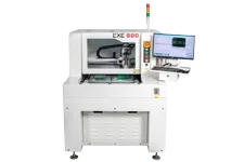
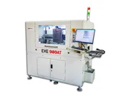
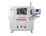
The EXE 880 Offline PCB Depaneling Machine uses high-speed router cutting, CCD vision positioning, dual worktables, cutter monitoring, and dust extraction. It is suitable for manufacturers requiring flexible standalone production, frequent product changeovers, and controlled PCB routing.
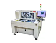
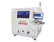
The EXE 960 Offline Laser Depaneling Machine uses non-contact laser processing and can be evaluated for communication PCB applications where very low mechanical stress, high precision, or narrow cutting paths are important.
Technical Guide: Learn more about spindle performance, PCB cutting accuracy, CCD alignment, router-bit condition, and dust extraction in How Does a PCB Depaneling Machine Achieve Clean and Precise Cuts?
Before selecting a depaneling system, EXE recommends reviewing the actual PCB and production requirements. Useful information includes:
PCB material and board thickness
PCB and panel dimensions
Cutting drawing, DXF, or routing-path information
Minimum component clearance from the PCB edge
Required production cycle time and daily output
Mechanical-stress and cutting-quality requirements
Dust-control requirements
Offline or inline production requirements
Barcode, MES, traceability, or production-line integration requirements
Router depaneling is suitable for many rigid 5G PCB assemblies and provides flexible cutting paths and efficient production. Laser depaneling may be considered when very low mechanical stress, high precision, narrow cutting paths, or material-specific requirements are priorities.
Yes, router depaneling can be suitable for many rigid RF and communication PCB assemblies when the fixture, router bit, spindle speed, feed rate, cutting depth, and dust extraction are correctly configured for the PCB material and layout.
Excessive PCB bending or cutting force can transfer mechanical stress to solder joints, connectors, RF components, and other sensitive areas. Stable fixturing, accurate routing, sharp tools, and suitable cutting parameters help reduce unnecessary mechanical stress.
Routing dust is typically controlled by extracting debris close to the cutting point. Extraction airflow, suction position, enclosure sealing, fixture design, filters, and regular maintenance all influence dust-removal performance.
Useful information includes PCB material, thickness, panel dimensions, cutting drawing, component clearance, expected production volume, cycle-time requirement, dust-control needs, and whether the machine will operate offline or as part of an automated production line.
Communication and 5G PCB depaneling requires careful control of cutting accuracy, mechanical stress, PCB positioning, tool condition, dust extraction, and production repeatability. Router and laser technologies can both be used depending on the PCB structure and manufacturing requirements.
EXE provides offline and inline PCB depaneling solutions for 5G base stations, RF modules, optical communication equipment, network electronics, and other communication PCB applications.
Discuss Your Communication PCB Depaneling Application
Send EXE your PCB material, thickness, panel drawing, component clearance, expected production volume, and cycle-time requirement. Our team can help evaluate the appropriate router or laser depaneling solution for your application.
Request a PCB Depaneling Evaluation