𐄀 Focus on providing PCBA separator manufacturing process solution

CAPACITY PLANNING FOR PCB ROUTING
Do You Actually Need a Faster PCB Router — or Is Routing Not the Bottleneck?
When a PCB production line misses its output target, it is easy to assume that the depaneling machine needs a faster spindle or more cutting capacity. In practice, total output may also be limited by panel feeding, vision alignment, PCB transfer, fixture handling, product discharge, changeover, or another process upstream or downstream.
The correct starting point is therefore not spindle RPM. It is the relationship between customer demand, takt time, observed depaneling cycle time, and the percentage of that cycle actually consumed by PCB routing.
These three numbers answer different questions. Mixing them together can lead to the wrong PCB depaneling-machine decision.
DEMAND-DRIVEN
Takt Time
How frequently a good PCB or panel must be completed to satisfy required production demand.
PROCESS-DRIVEN
Cycle Time
The observed time required for the depaneling process to complete one repeated production cycle.
CUTTING-DRIVEN
Routing Time
The portion of the cycle during which the router bit is actually following the programmed PCB cutting path.
The Lean Enterprise Institute defines takt time as available production time divided by customer demand. Its cycle-time reference defines cycle time as the time required to produce a part or complete a process based on actual measurement.
Takt time starts with demand, not machine capability.
TAKT TIME
Available Production Time ÷ Required Production Quantity
For example, assume an SMT line has 420 minutes of actual available production time per shift and must deliver 480 good PCB assemblies.
Illustrative Example
Available time = 420 minutes × 60 = 25,200 seconds
Demand = 480 good assemblies
Takt Time = 25,200 ÷ 480 = 52.5 seconds
In this example, the production system must complete approximately one good assembly every 52.5 seconds to satisfy the required output.
Important: This is a calculation example, not an EXE machine cycle-time specification. Actual depaneling time must be measured using the real PCB, panel layout, cutting path, fixture, machine program and material-handling configuration.
This is one of the easiest mistakes to make when sizing a PCB depaneling machine. The router normally receives a panel, while the factory's production target may be expressed in individual PCB assemblies.
Convert the demand before comparing it with machine cycle time
Required individual PCBs per shift
÷ Number of good PCBs per panel
= Required panels per shift
If one panel contains 8 usable PCBs and demand is 800 PCBs per shift, the depaneling process must handle approximately 100 successful panels per shift before allowances for verified yield losses, stoppages or other production conditions are considered.
A PCB router is not cutting during every second of the production cycle. For an inline machine, the complete cycle may include several separate operations.
| Time Element | What It Includes | What Can Change It |
|---|---|---|
| Panel Feeding | Receiving the panel from the conveyor or loading station | Conveyor speed, upstream handoff, panel dimensions |
| Transfer & Placement | Moving the PCB or fixture to the cutting position | Travel distance, servo motion, pickup strategy |
| Vision Alignment | Mark recognition and coordinate correction | Number of reference points, imaging sequence, program |
| Router Cutting | Actual programmed material-removal time | Total routing length, feed rate, path strategy, number of tabs and PCB geometry |
| Output / Unloading | Removing and transferring separated PCBs | Output method, downstream equipment, carrier handling |
| Allocated Changeover Time | Program, fixture, tool or product changeover allocated across production quantity | Product mix and batch size |
Lean Enterprise Institute also distinguishes effective machine cycle time from machine-only time by considering loading, unloading and allocated changeover time. This is useful when analyzing PCB depaneling because the spindle is only one part of the complete production cycle.
Router cutting time is strongly influenced by the actual cutting path. Two PCB panels with the same outside dimensions can require very different routing times if one contains more PCBs, more breakaway tabs, longer contours, or a more complex tool path.
Simplified routing-time concept
Routing Time ≈ Effective Cutting Distance ÷ Validated Cutting Feed Rate
Plus any non-cutting spindle travel, entry/exit motion, repositioning and program-specific movements required by the actual machine cycle.
This formula should be used only as an initial estimate. Feed rate cannot be selected only to reduce cycle time. It has to be validated against PCB material, board thickness, cutter diameter, spindle speed, cutting depth, edge-quality requirements and mechanical stress.
For cutting-parameter considerations, see our PCB Router Bits for Depaneling Guide.
Assume the calculated takt time is 52.5 seconds per production unit. During a trial, the observed depaneling cycle is measured as follows.
| Operation | Illustrative Time |
|---|---|
| Panel feeding / transfer | 6 s |
| CCD positioning | 2 s |
| PCB routing | 32 s |
| Transfer / product output | 7 s |
| Observed Cycle Time | 47 s |
47 s Cycle Time < 52.5 s Takt Time
In this simplified example, the depaneling process is theoretically fast enough to meet the required takt. A dual-spindle router would not automatically be necessary only because a higher-capacity machine exists.
Now assume the same product requires a longer routing path and the routing portion increases from 32 seconds to 45 seconds.
New cycle estimate
6 s Feed + 2 s Vision + 45 s Routing + 7 s Output
= 60 seconds
The process is now slower than the 52.5-second takt requirement. More importantly, routing consumes most of the total cycle. This is the type of situation where engineers should investigate whether routing can be optimized or whether additional processing capacity is justified.
| What Consumes the Cycle? | First Question | Possible Direction |
|---|---|---|
| Routing | Is the cutting path or feed strategy the constraint? | Optimize path/tooling or evaluate additional spindle capacity |
| Loading / Transfer | Is the spindle waiting for material? | Improve automation or material-handling sequence |
| Vision / Positioning | Is alignment taking an unusually large share of the cycle? | Review Mark strategy, fixture repeatability and program setup |
| Product Output | Is downstream equipment preventing the router from releasing the next product? | Review line balance and downstream interface |
| Changeover | Is high-mix production losing too much time between products? | Improve fixture, program and tool changeover strategy |
Spindle count should be selected from the process bottleneck. A dual-spindle router is most useful when routing consumes a substantial part of the cycle and the cutting workload can actually be organized across separate processing areas.
Single-Spindle Inline Router
Consider a single-spindle system when routing time already fits comfortably within takt and additional spindle capacity would not remove the true bottleneck.
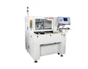
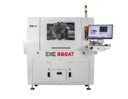
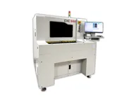
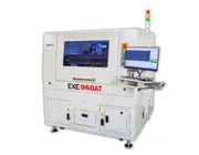
The EXE 880AT Inline PCB Depaneling Machine is an example of an automated single-spindle routing configuration.
Dual-Spindle Inline Router
Consider a dual-spindle architecture when routing is a verified cycle-time constraint and the actual PCB program can use two processing areas effectively.
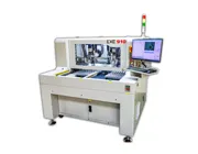
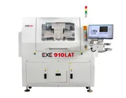
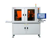
The EXE 910LAT Inline Dual-Spindle PCB Depaneling Machine is designed around two spindle processing areas and automated inline PCB handling.
Two Spindles Do Not Automatically Mean 2× Throughput
A dual-spindle machine may increase available routing capacity, but total line output is still affected by panel feeding, transfer, CCD positioning, fixture handling, routing-path distribution, cutter condition and downstream material flow.
If a 60-second cycle contains only 10 seconds of routing and 50 seconds of handling or waiting, doubling spindle capacity cannot remove the majority of that cycle. If routing consumes most of the cycle, the potential value of additional routing capacity becomes much greater.
Once an observed cycle time is known, a simple theoretical hourly rate can be calculated:
Theoretical Cycles per Hour = 3600 ÷ Observed Cycle Time (seconds)
For a measured 45-second cycle, the mathematical rate is 80 cycles per hour. That does not mean the machine should automatically be quoted as delivering 80 good production cycles every hour under every condition.
Sustainable capacity should also consider actual tool changes, fixture or program changeovers, planned maintenance, production interruptions, quality losses, material availability and process variability. These values should come from real production data rather than from an arbitrary assumed efficiency percentage.
Lean Enterprise Institute's standardized-work resources describe the use of process-capacity sheets to evaluate machine cycle times, setup and tool-change intervals, and manual work time when identifying process bottlenecks.
If routing is identified as the constraint, the next question is whether capacity must be added or whether the existing process can first be improved.
Review Non-Cutting Travel
Excessive spindle repositioning between tabs and cutting areas can add time without performing material removal.
Review the Cutting Sequence
Tool-path order should balance efficient motion with PCB support, separation stability and final-tab behavior.
Validate the Feed Rate
Feed rate should be optimized within acceptable cutting quality, tool-life and mechanical-stress limits rather than increased only to shorten cycle time.
Check Fixture and Panel Design
Fixture access, tab location and panel geometry can affect both cutting movement and how efficiently the PCB can be loaded and removed.
Check Router-Bit Condition
A process should not compensate for a worn cutter simply by changing feed or motion settings. Tool condition and cutting parameters need to be evaluated together.
Panel geometry also affects routing distance and fixture strategy. See our PCB Panelization Design for Automated Depaneling for guidance on routing channels, tabs, tooling holes and component clearance.
Offline and inline PCB routers can use the same cutting technology while having very different production constraints.
| Capacity Factor | Offline Router | Inline Router |
|---|---|---|
| Loading | Operator or workstation workflow | Upstream conveyor and automatic handling |
| Bottleneck Risk | Operator availability, loading and fixture changeover | Line balance, upstream/downstream handoff and routing capacity |
| Capacity Target | Often optimized around workstation output and product mix | Must be coordinated with the takt of the connected production line |
| Changeover | Often important in high-mix production | Important when different PCB models share the same automated line |
A useful capacity study needs more than a target such as “1,000 boards per hour.” The supplier needs enough PCB and production information to understand how that demand translates into an actual depaneling cycle.
✓ PCB / PCBA panel drawing
✓ Number of PCBs per panel
✓ Total routing length / cutting path
✓ PCB material and thickness
✓ Router-bit diameter
✓ Target output per shift / hour
✓ Actual available production time
✓ Product changeover frequency
✓ Upstream / downstream equipment
✓ Required output and handling method
A Simple Router-Capacity Decision Rule
Cycle Time comfortably below Takt: existing routing capacity may already be sufficient.
Cycle Time close to Takt: evaluate process variation, tool changes and production interruptions before assuming sufficient capacity.
Cycle Time greater than Takt: identify which part of the process is creating the deficit.
Routing is the dominant bottleneck: optimize the routing process first, then evaluate additional spindle or machine capacity if necessary.
Divide the actual available production time by the required production quantity for the same period. Make sure the unit of demand is consistent — for example, panels per shift or individual PCBs per shift.
Total cycle time can include feeding, transfer, vision alignment, actual routing, separated-PCB handling, output and allocated product-changeover time. Routing time itself is affected by cutting distance, tool path, feed rate, PCB geometry and process parameters.
A dual-spindle architecture is worth evaluating when routing is a verified production bottleneck and the PCB routing workload can be distributed effectively between two processing areas.
No. Maximum spindle RPM is not the same as validated cutting feed rate, and the total depaneling cycle also contains non-cutting operations. Cutting parameters must remain compatible with PCB material, tool diameter, edge-quality requirements and process stability.
Size the PCB router from the bottleneck, not the brochure
Takt time tells you how quickly production must run. Cycle time tells you how quickly the depaneling process actually runs. Routing time tells you whether the cutter is the reason those two numbers do not match.
Only after those three values are understood does it make sense to decide whether the process needs path optimization, faster material handling, a different fixture strategy, a single-spindle inline router, a dual-spindle system, or additional machine capacity.
Not Sure How Much PCB Routing Capacity You Need?
Send EXE your PCB panel drawing, number of PCBs per panel, routing path, material and thickness, required output, available production time and target takt time. We can evaluate whether routing is likely to become the bottleneck and whether an offline, inline, single-spindle or dual-spindle depaneling configuration should be considered.
Request a PCB Capacity Evaluation